The Lakhs-Sized Mistake of Treating AC and Wiring as an Afterthought
A high-rise residential project. The architect designs beautiful false ceilings in the common areas — clean, minimal, 200 mm of height loss. Approved. Construction starts. Three months in, the MEP contractor arrives, looks at the 200 mm of space available, and lists what has to fit inside it: oval AC ducts at least 450 × 300 mm, electrical conduits, a sprinkler system, return-air ducting. The architect looks back in panic.
The "solution" is to drop the ceiling to 600 mm — eating 400 mm of height on every floor. The building looks squat, the client is furious, and the architect gets blamed. The real culprit was never the MEP system. It was designing the building without ever asking the MEP consultant where the systems would go.
The ceiling space that does not exist
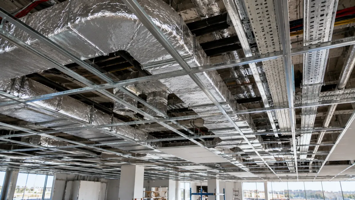
The first question to answer before drawing a false ceiling is: what goes in this space? Add it up honestly for a typical Indian building — about 400 mm for return-air ducting, 50 mm for electrical conduit, 50 mm for sprinkler pipe, 100 mm for hangers, 150 mm for recessed lights, 50 mm for acoustic board. That is roughly 800 mm minimum, before anyone has thought about a single bend or crossing. Architects routinely design 200–300 mm and are then shocked that it is impossible.
The fix is almost embarrassingly simple: before you draw the ceiling, ask the MEP consultant for the minimum depth, then design to it. If 600 mm is needed and that forces a taller inter-floor height, you decide that at the design stage, when it is cheap — not three months into construction, when it is brutally expensive.
When AC ducts eat your false ceiling
Air conditioning is one of the biggest space-eaters in Indian buildings. A single room's return duct is around 400 × 300 mm. Now imagine a 20-unit floor where every unit's return runs through the common-corridor ceiling — twenty ducts, some parallel, some crossing, some turning. The space fills fast. The wrong approach is the architect designing for a 400 mm ceiling while the MEP consultant silently assumes 800 mm; during construction, one of them is wrecked. The right approach has the consultant in the room during schematic design, telling you "for a shared-return 20-unit floor I need 700 mm minimum" — so you can choose to raise the floor height, change the AC strategy, or route ducts through a vertical shaft, with the cost understood upfront.
The coordination failure that costs tenants their walls
One office tower needed a 100 mm fire riser carrying water from the terrace tank to the ground floor, with an isolation valve every floor. The architect provided no vertical service shaft, so the riser had to run through tenant spaces, and the valves stuck 150 mm into every room. The tenants complained; the architect was asked to "hide" a riser that had nowhere to hide. The cause: the MEP consultant was brought in after the building was designed, to fit systems into spaces that no longer existed.
The cure is three disciplines:
- The MEP consultant joins on day one — not after the architecture is frozen, not in the construction phase.
- MEP is drawn on the architectural plans — major ducts, pipes and shafts are part of the design, not an afterthought bolted on later.
- Coordination drawings before construction — architecture, structure and MEP overlaid on one sheet so a duct trying to occupy a column, or a pipe clashing with the staircase, is caught on paper, not on site.
Fire safety: the system that arrives last and fits nowhere
Fire safety is the classic last-minute addition. Architect designs the building, MEP adds AC and water, and the fire consultant is called in last — by which point there is no space left for detection, sprinklers, emergency lighting, fire-rated assemblies, hydrants and stair pressurisation. A 10,000 sqm building has kilometres of sprinkler pipe to route. The fix is to read the NBC before you design — sprinkler coverage, stairwell widths, exit distances, dedicated fire circuits — and allocate the space from the start.
Integrating MEP from day one — the right sequence
Done properly, MEP threads through every phase: preliminary space requirements at concept stage; major ducts, pipes and shafts located during schematic design; full clash-resolved coordination drawings in design development; specifications and access points in the construction documents; and on-site, every system inspected and tested before it is covered by ceiling, plaster or flooring. It costs more in design time. It saves vastly more in construction chaos — and it produces a building where everything actually works.
How an integrated partner prevents the lakhs-sized mistake
Every failure above comes from the same root: the people designing the architecture and the people designing the HVAC, electrical, plumbing and fire systems are strangers who meet too late. At Secured Engineers Pvt. Ltd., MEPF is not a sub-trade fitted in afterwards — it is engineered alongside the architecture and approvals from concept stage. Ceiling depths are sized to the systems that must fit, ducts and risers are coordinated on paper, clashes are resolved before anyone casts a slab, and systems are tested before they are concealed. One team owns Mechanical, Electrical, Plumbing and Fire, so there is no consultant arriving in month three to tell you it cannot be done.
This is one of the twenty pain points Er. Ankur Kaplesh confronts in From AutoCAD to Actual Site. Get notified at launch, and if you want MEP designed into your building instead of squeezed in later, get a free MEP quote.
More insights
VRF vs Chiller Plant: Which HVAC System Should You Choose in India?
A direct, India-specific comparison of VRF and chilled-water plants — by capacity, running cost, plant room, payback and the building types each one suits best.
Solar EnergyWhy Most Industrial Solar Underperforms (It Starts on Day 1)
Solar is not a product you buy — it is an engineering outcome. The decisions made before a single panel goes up quietly decide whether your plant saves money or loses it for 25 years.