
Fire Alarm System Expansion: Loop Capacity, Compatibility and Testing
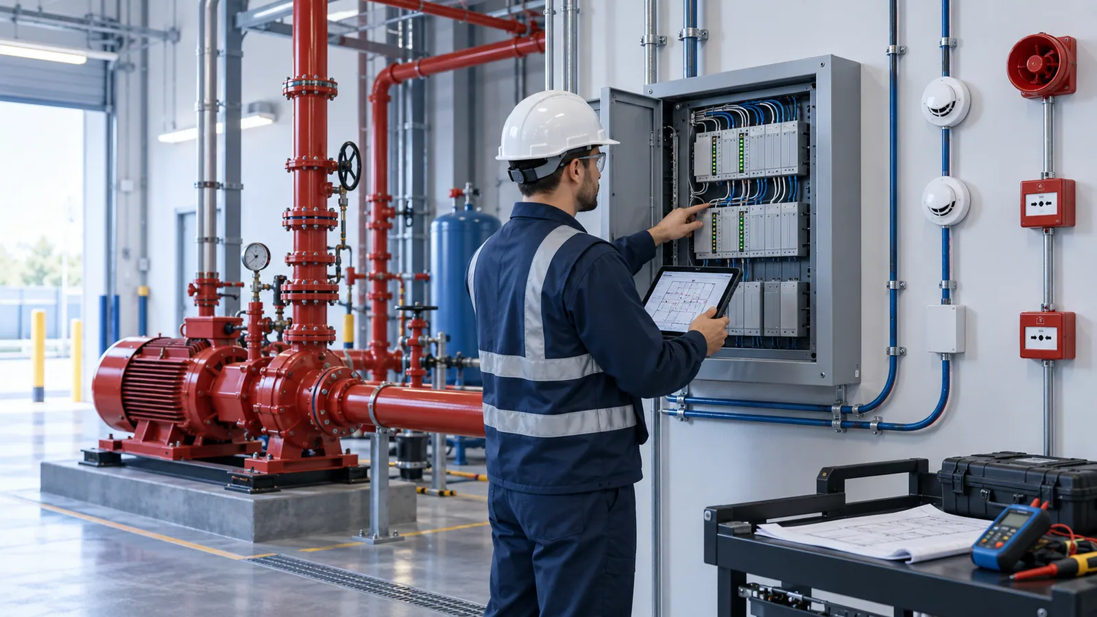
Most fire alarm extensions are scoped as "add detectors to the new area". That description hides the questions that decide whether the extension works: whether the existing panel and loops have the capacity, whether the new devices can talk to the old panel at all, whether the batteries still cover the system once sounders are added, and whether the cause-and-effect — what an alarm actually does to fans, dampers, lifts, doors and voice messages — has been extended along with the wiring.
Two reference points are worth confirming first. BIS has published IS 2189:2026, the fifth revision of the code of practice for selection, installation and maintenance of automatic fire detection and alarm systems, superseding the 2008 edition that many existing systems were designed to. And whether a building needs detection at all, and of what kind, is set by NBC 2016 Part 4 for its occupancy — the BIS guide to the Code points to Part 4's Table 7 for the requirements for fire-fighting installations — and by the state fire authority. Ask the authority which edition and which requirements it will apply to the extension before scoping it.
Panel and loop capacity
On an addressable system the binding limit is rarely the headline "devices per loop". The panel manufacturer's documentation sets several limits at once, and the extension has to fit inside all of them:
- Addresses per loop — detectors, call points and input/output modules each take an address, and some panels count modules separately.
- Loop current and cable length — sounders, beacons and modules powered from the loop draw current, and a long loop with many loop-powered sounders can run out of voltage at the far end well before it runs out of addresses.
- Short-circuit isolation — new devices must sit between isolators so that a single cable fault cannot disable more of the system than the design allows.
- Panel hardware and firmware — free loop-card slots, network node limits, zone and output limits, and the firmware version, which may need upgrading before the panel will recognise newer device types.
- Power supply and batteries — standby and alarm loads recalculated with every added sounder, beacon and module, so that the battery still supports the standby period and then the alarm period the design standard requires.
Conventional systems have their own version of the same limits: detectors per zone, the number of zones, end-of-line arrangements and sounder-circuit loading. Either way, record what is on the system today before deciding what to add; the panel's event log and loop printout are the starting point.
Panel and loop capacity checklist
| Check | Where to find it | Why it limits the extension |
|---|---|---|
| Panel make, model and firmware | Panel label, configuration software, O&M manual | Decides which devices and features the panel will accept |
| Loops installed and free slots | Panel hardware and loop cards | A new loop is often better than overloading an old one |
| Addresses used on each loop | Loop printout or device schedule | Spare addresses are the first limit |
| Loop loading and cable length | Manufacturer's loop calculation; as-built cable routes | Voltage at the far end limits loop-powered sounders and modules |
| Isolator positions | As-built loop drawings | New devices must not widen what a single fault can disable |
| Zones and outputs | Panel configuration file | Zone and output limits cap new areas and new interfaces |
| Network nodes and repeater panels | Network drawing | Adding a panel or repeater may exceed the network limit |
| Power supply and battery calculation | Original calculation; battery test results | Added sounders change both the standby and the alarm load |
| Sounder and voice evacuation zones | PA/VA drawings; cause-and-effect matrix | New areas need the same evacuation signal and messages |
| Cable type and condition | Insulation and earth-fault test results | Cabling with persistent earth faults should not be extended |
| Configuration access | Who holds the software, licences and passwords | Without access, every change goes through the original vendor |
Product compatibility
Addressable protocols are proprietary. As a rule, detectors and modules work only on the panel family they were made for, and only those the panel manufacturer lists as compatible should be connected. A detector from another brand with the "same" specification is not a substitute: it may not be recognised at all or, worse, recognised only in part. Before buying anything, get the manufacturer's compatibility list for the installed panel and firmware, and confirm that the product line is still supported. An end-of-life panel is better replaced before the building grows around it than after.
Three further checks:
- Product standards and certification. Control and indicating equipment and power supply equipment have their own BIS product standards — IS/ISO 7240-2:2017 and IS/ISO 7240-4:2017 — and smoke detectors are covered by IS 11360. Check what your specification and the fire authority require, and whether the device types you are adding fall under a BIS compulsory-certification order at the time you buy.
- Detector selection for the new space. A kitchen, a boiler room, a dusty process bay and a high-bay warehouse each need the right detector type; the wrong one in a new area becomes a source of false alarms for the whole building.
- One evacuation signal. Sounders in the new area must give the same evacuation signal as the existing ones (BIS sets out the signal in IS 13735:2023, Audible emergency evacuation signal requirements), and voice messages must be extended zone by zone.
Cause-and-effect interfaces
The cause-and-effect matrix is the system's real specification: every input — detector zone, call point, sprinkler flow switch, suppression release — against every output it must trigger. An extension adds rows and columns:
- alarm sounders and voice evacuation zones;
- AHU shutdown, fire and smoke dampers, and staircase pressurisation or smoke-extraction fans;
- lift homing and fire-mode operation — NBC 2016 Part 8 Section 5 covers the fire-protection requirements for lifts;
- access-control door release on escape routes;
- gas shut-off for kitchens and process gases;
- signals to the fire command centre, where NBC 2016 Part 4 requires one, and to the building management system;
- monitoring of fire pumps and sprinkler valves.
The trap is the shared output. A new AHU that serves both old and new areas, or a staircase whose pressurisation fan now protects an extra floor, changes existing rows, not only new ones. Every interface also has another contractor on the far side — HVAC, lifts, access control, gas — so the matrix has to name who wires each relay and who witnesses each test. Our guide to integrating ELV systems covers the same problem from the security side.
Extend, network or replace — decision table
| Option | Fits when | Watch for | Testing it needs |
|---|---|---|---|
| Add devices to existing loops | Spare addresses and loop loading; supported panel; a small area | Voltage at the far end of the loop; isolator spacing; battery capacity | New devices; loop isolator test; the cause-and-effect lines affected |
| Add loop cards to the existing panel | Free slots and supported firmware; the area is too big for the existing loops | Panel power-supply capacity; zone and output limits | New loops end to end; power supply and battery test; full cause-and-effect for the new zones |
| Add a networked panel of the same family | A large extension or a separate building; network capacity available | Network limits; matching software versions; one point of control | Network fault tests; cross-panel cause-and-effect; fire command centre and repeaters |
| Replace or migrate the system | Panel end-of-life; no compatible devices; no configuration access; recurring faults | Keeping the building protected throughout a phased change-over; what cabling can be reused | Full re-commissioning of the whole building |
| Separate stand-alone system | Rarely — only where the authority accepts it and the interfaces are hard-wired | Two panels and two sets of alarms; confusion in an emergency | Interface tests between the systems; a joint evacuation test |
Integrated tests and record updates
Testing an extension has three layers, and only the last proves the system works:
- Device tests — every new detector tested by the method suited to its type, every call point operated, and every module checked at the panel for the right address and location text.
- System tests — isolator operation (a deliberate short shows the devices on both sides still reporting), earth-fault and open-circuit indication, battery capacity against the recalculated load, and sounder audibility in the new areas and in any existing area whose sounders changed.
- Integrated cause-and-effect tests — each line of the matrix triggered and its outputs observed in the field: the AHU stops, the damper closes, the lift returns, the door releases, the message plays, the signal reaches the fire command centre. Run them with the HVAC, lift and access-control contractors present, and repeat the existing lines the extension touched.
Then update the records, because the next fault-finder and the next inspection will rely on them: the device schedule with addresses and locations, as-built loop drawings, zone charts at the panel, the revised cause-and-effect matrix with a revision number, the battery calculation, a backup of the panel configuration, test certificates and operator training. The extension also adds to the maintenance load — more devices to test every year — which is worth re-estimating with the MEP maintenance budget calculator and writing into the AMC scope.
The fire authority decides whether the extension needs a revised approval or is taken up at the next renewal; ask before the work starts rather than at the renewal inspection. No test record makes a system "compliant" — it shows what was tested, how, and with what result. Our fire protection scope covers addressable and conventional detection and alarm, installation, testing and the fire-NOC documentation. To have an extension reviewed, request a scope review with the approved fire layout and the proposed changes; other guides for projects at this stage are grouped under Plan by project stage.
Sources and how to verify
- IS 2189:2026, Selection, installation and maintenance of automatic fire detection and alarm system — code of practice (fifth revision) — BIS standards portal; supersedes IS 2189:2008.
- IS/ISO 7240-2:2017 (control and indicating equipment), IS/ISO 7240-4:2017 (power supply equipment), IS 11360 (smoke detectors) and IS 13735:2023 (audible emergency evacuation signal) — BIS, listed on the BIS standards portal.
- National Building Code of India 2016 — BIS. Part 4 (fire and life safety, including the fire command centre) and Part 8 Section 5 (lifts).
- Guide for Using National Building Code of India 2016 — BIS. Points to Table 7 of Part 4 for the requirements for fire-fighting installations.
Confirm locally: which edition of IS 2189 and which requirements the state fire service will apply to the extension, and whether a revised approval is needed; the panel manufacturer's compatibility list, loop calculation and firmware requirements for the installed panel.
Frequently asked
What information is needed before extending an existing fire alarm system?
The panel make, model and firmware; a loop printout or device schedule showing the addresses used on each loop; as-built loop and cable drawings; the cause-and-effect matrix; the original battery calculation; the approved fire drawings and current fire NOC; and, for the new area, its use, ceiling heights and environment. Without the loop data and the matrix, any price for the extension is a guess.
Which existing-system conditions turn a fire alarm extension into a panel replacement?
A panel or protocol the manufacturer no longer supports, no compatible devices for the new areas, no free loops and no slots for more, firmware that cannot be upgraded, configuration software or passwords held by a vendor who has gone, cabling with persistent earth faults, or an extension too large for the existing power supply and network.
What should we send for a fire alarm extension review?
The approved fire layout, the proposed changes marked on drawings, the building particulars — occupancy, height and floor areas — the panel details and loop printouts, the cause-and-effect matrix and the latest maintenance or test reports. Those let an engineer judge capacity and compatibility before anyone visits the site.
Can we add another brand’s detectors to our addressable loop?
Usually not. Addressable protocols are proprietary, and only devices the panel manufacturer lists as compatible with your panel and firmware should be connected. A cheaper detector that the panel only partly recognises is a fault waiting for a fire.
Related services
More insights
Grease Fires Don't Ask Permission. Does Your Kitchen Hood Have a Suppression System?
Commercial kitchen fires start where general fire codes barely look — the exhaust hood, the grease-laden ductwork, the fryer line. A hotel or restaurant kitchen needs its own dedicated fire suppression system, its own exhaust cleaning schedule and its own inspection regime, distinct from the building's general fire protection. Most hotels discover the gap during an insurance audit, not before.
Fire SafetyHow should a factory plan fire pump capacity?
Pump capacity is decided by the hazard and the code, not the budget or a standard set. A decision framework: demand, pressure, redundancy, the tank, and the room — in that order.
More on Fire Safety · all insights