
Industrial Exhaust System Design: Define the Process Before the Fan
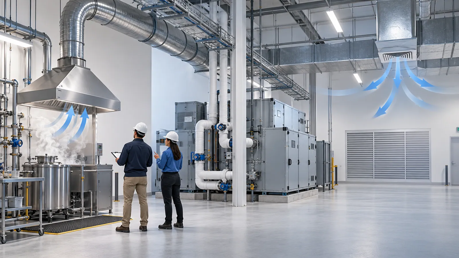
An industrial exhaust system should capture a contaminant where it forms and carry it safely to an air cleaner or a discharge point. The design starts with the process, not a fan catalogue: what is released, where, how and how often. Choose the fan first and you are guessing at everything that decides whether it works. This guide covers capture versus air changes, duct and filter losses, the hazardous processes that need specialist input, and the discharge and commissioning scope to write into the contract.
1. Contaminant capture versus air changes
General (dilution) ventilation mixes clean air into the whole room and removes it again. It suits heat and low-level, widely spread contaminants. Local exhaust ventilation captures the contaminant at the source, before it reaches the operator's breathing zone. NBC 2016 Part 8 gives recommended air changes and contaminant limits for ventilation air, but a room air-change figure does not size the capture of a fume plume at a welding bench or a powder tip. That airflow depends on the contaminant, how it is released, the distance from the hood and the cross-draughts around it.
Start with a process survey. Walk the line with operations and maintenance staff, mark each source on a current plan, and record it against this checklist.
| Record for each source | Why it matters |
|---|---|
| What is released: dust, fume, vapour, gas, mist, heat or odour | Sets the capture method, duct velocity, air cleaning and duct material |
| Whether it is flammable, combustible, toxic or corrosive | Brings in the specialist checks in section 3 |
| How it is released: a rising plume, thrown particles, slow evaporation | Decides the hood type: enclosing, capturing or receiving |
| Continuous or intermittent, and which machines run at the same time | Sets the design flow and the diversity between branches |
| Operator position and the access the task needs | A hood the operator has to work around gets moved or removed |
| Cross-draughts from doors, supply-air outlets, fans and moving equipment | Draughts carry the contaminant past the hood |
| Temperature and moisture of the airstream | Condensation, duct material and fan selection |
| Process changes planned in the next few years | A future machine in the wrong place makes a well-sized system hard to use |
| Routes for ducts, service access and a discharge point | Duct length and fittings set the fan duty |
The hood follows from the release. An enclosing hood surrounds the source; a capturing hood draws the contaminant towards an opening; a receiving hood sits in the path of a plume that already moves in a known direction, such as the heat rising off a hot tank. Ask suppliers to show each hood position and the capture basis behind it, and how the operator reaches the work without blocking it.
2. Duct and filter losses decide the fan
- Velocity and size. Airflow equals duct velocity multiplied by duct area (Q = V × A). A duct that is too large lets dust settle; one that is too small raises resistance and fan energy.
- System resistance. Set the flow at each hood, combine the branches that run together, then add the resistance of duct length, elbows, branches, dampers, the air cleaner and the stack. Select the fan at that airflow and pressure, not by a headline motor rating.
- Filters load up. A filter's pressure drop rises as it collects dust, so the fan has to deliver the design airflow at the filter's design final pressure drop, not only when the filter is clean. A differential pressure gauge across each filter tells operators when to clean or change it.
- Balance by design. Dampers can trim branches, but they cannot fix a poorly placed hood or an undersized fan.
- Materials. Galvanised sheet is common; corrosive vapours, hot air or abrasive dust may need other materials or linings. The specification should state the material for each section.
- Air cleaning. Choose it for the contaminant and for where the air goes next: cyclones and bag filters for particles, a treatment method suited to the gas for vapours and gases.
- Make-up air. Every cubic metre exhausted must be replaced. Plan where replacement air enters so it does not blow across the hoods, keep the intended pressure relationship with neighbouring rooms, and include the heating or cooling load of that air in the HVAC design.
- Energy. Exhaust fans run long hours. Variable frequency drives on fans are among the measures in the Bureau of Energy Efficiency's retrofit guidance, but they need a control sequence that keeps capture and room pressure at part load.
The ventilation and air-change calculator gives a first general-ventilation airflow for a room; capture at each hood still has to be designed from the process.
3. Hazardous processes need specialist requirements
Some processes put the exhaust system itself at risk. These are not decisions for the ventilation contractor alone; the process owner, a specialist and, where licensing applies, the authority decide them.
- Flammable vapours and gases (painting, solvent cleaning, fuel handling). The area is classified into hazardous zones, and fan motors, controls and lighting must be suitable for the zone. In premises covered by the Petroleum Rules, 2002, rule 102 requires electrical apparatus in those areas to be approved by the Chief Controller of Explosives at the Petroleum and Explosives Safety Organisation (PESO). The airflow should keep vapour concentrations well below the flammable range.
- Combustible dusts (flour, sugar, wood, some plastics, and metal powders such as aluminium). Collectors and ducts can carry an explosion risk; explosion venting or isolation, earthing and bonding, and duct velocities that stop dust settling are specialist decisions.
- Toxic or corrosive fumes (plating, pickling, chemical processing). Corrosion-resistant ducts and fans, scrubbing where required, and ductwork inside the building kept under negative pressure so any leak is inward.
- Hot processes (furnaces, ovens, heat treatment). High-temperature materials, allowance for expansion, and fire separation where ducts pass through fire-rated walls.
- Commercial kitchens. Grease-laden exhaust is a fire risk, with its own filtration, cleaning access and suppression requirements; see our guide to kitchen exhaust and fire suppression.
4. Discharge and commissioning scope
Discharge the cleaned air away from air intakes, openable windows and neighbouring buildings, at a height and velocity that carry it clear of the roof. Where the Air (Prevention and Control of Pollution) Act, 1981 applies, the State Pollution Control Board's consent can specify the control equipment and the chimney the plant must install, so design to the consent conditions; our CTE and CTO guide covers the process.
Write the acceptance checks into the purchase scope before work starts:
- Testing, adjusting and balancing (TAB). Measure the airflow at each hood and branch and the fan duty, then adjust to the agreed design basis.
- Capture checks. Show with smoke visualisation that each hood captures under real working conditions, with doors and nearby equipment operating.
- Baseline readings. Record the static pressure at each hood and across each filter; they are the reference for every later check.
- Fan and interlock checks. Rotation, motor current, vibration, and any interlock that stops a process starting without its exhaust.
- Handover. Design airflow for each capture point, fan and filter details with pressure-drop limits, as-built drawings, operation and maintenance instructions, and who maintains filters and ducts.
Check access before approving the layout: staff need a safe route to filters, dampers and fans. Then use this table to scope each process before the fan is chosen.
| Process | Capture approach | Air cleaning and ducts | Specialist check | Discharge check |
|---|---|---|---|---|
| Welding and soldering fume | Capturing hood or extraction arm close to the work | Filter suited to fine fume; spark arrestor ahead of the filter | Fire risk from sparks reaching the filter | Away from intakes; any consent conditions |
| Grinding, cutting and machining dust | Enclosing or capturing hood shaped to the particle throw | Velocity that keeps dust moving; cyclone or bag filter | Combustible metal dusts need an explosion assessment | Collector location and dust disposal |
| Solvent vapour: painting, coating, cleaning | Booth or enclosing hood that keeps vapour below the flammable range | Ducts and fans suitable for flammable vapour | Hazardous-area zoning; equipment for the zone; PESO approval where the Petroleum Rules apply | Treatment or dispersion as the consent requires |
| Powder handling, mixing and bag tipping | Enclosing hood at tipping and transfer points | Bag or cartridge filter, with explosion protection where the dust is combustible | Combustible-dust assessment; earthing and bonding | Collector siting; consent conditions |
| Acid and corrosive fumes: plating, pickling | Lip or push-pull extraction at the tanks | Corrosion-resistant ducts and fan; scrubber | Chemical compatibility; scrubber effluent | Scrubber discharge and effluent route under the consent |
| Hot processes: furnaces, ovens | Receiving canopy over the rising plume | High-temperature materials; expansion allowance | Fire separation at wall and floor crossings | Stack height and plume rise |
| Commercial kitchen | Canopy hood with grease filtration | Grease duct with cleaning access | Fire suppression as the fire design requires | Smoke and odour near neighbours |
Exhaust, general ventilation and make-up air belong in one design with the rest of the HVAC; our industrial HVAC design checks cover the wider review, and warehouse ventilation for expansion covers general ventilation in storage buildings. Design and installation sit under HVAC and mechanical (see ventilation, pressurisation and exhaust), commissioning and TAB under testing and commissioning, and a new factory or expansion can take it as part of a turnkey MEPF scope or factory MEPF. To scope yours, share the layout, operating schedule and existing HVAC data through a scope request; more planning guides are in Insights.
Sources and how to verify
- Bureau of Indian Standards, National Building Code of India 2016 (SP 7:2016), Part 8 Building Services: Section 1 (recommended air changes, contaminant limits for ventilation air) and Section 3 (mechanical ventilation for industries); summarised in the BIS Guide for Using NBC 2016.
- Bureau of Energy Efficiency, retrofit and energy-efficiency publications, including Energy Efficiency Solutions for Existing Buildings: Commercial (prepared by TERI for BEE, 2025), which lists variable frequency drives for fans among HVAC retrofit measures.
- Petroleum and Explosives Safety Organisation, Approval of Ex (electrical) equipment for use in hazardous areas: rule 102 of the Petroleum Rules, 2002, zone definitions and the IS/IEC 60079 series.
- India Code, Air (Prevention and Control of Pollution) Act, 1981: section 21, consent of the State Board and conditions on control equipment and chimneys.
Confirm locally: your consent conditions on emissions and stacks, the hazardous-area classification by a competent person, any licence your materials need, and the fire authority's requirements for kitchen and special-hazard systems.
Frequently asked
What should I document about a process before an exhaust system is designed?
For each source: what is released (dust, fume, vapour, gas, mist, heat), whether it is flammable, combustible, toxic or corrosive, how it is released, when it runs and which machines run together, where the operator stands, the draughts around it, the temperature and moisture of the airstream, planned process changes, and the possible duct routes and discharge point. Mark every source on a current plan; the process survey checklist in this guide sets it out.
Which plant conditions push up the cost of an industrial exhaust system?
Flammable vapours or combustible dust (equipment suited to hazardous zones, explosion protection), corrosive fumes (special duct materials and scrubbers), long or congested duct routes, emission and stack conditions in the pollution-board consent, a large make-up air load that has to be heated or cooled, high airstream temperatures, and installation inside a running plant. Each adds equipment, materials or sequencing that a fan-only quotation leaves out.
What should I send an engineer to scope a process exhaust system?
A layout with each source marked, a description of each process with safety data sheets for the materials, the operating schedule, photographs of the sources and operator positions, existing HVAC and exhaust data, the pollution-board consent conditions, the electrical capacity available, and any process changes planned. That is enough for an engineer to propose hood types, airflow basis and a fan duty for review.
How is exhaust airflow worked out for a factory process?
Hood by hood. Each capture point gets the airflow its contaminant, release pattern and distance need; flows are combined for branches that run at the same time; then duct sizes are checked for velocity (Q = V × A) and the whole route, including fittings, the air cleaner and the stack, is added up to give the fan duty. A room-wide air-change figure alone will not size source capture.
Does an industrial exhaust system need make-up air?
Yes. Air removed by exhaust must be replaced through a planned path. Poorly placed supply air can blow across a hood or pull air through doors and gaps, and the incoming air carries a heating or cooling load that belongs in the HVAC design from the start.
What should an exhaust-system handover include?
TAB results tied to each hood and branch, smoke-test evidence of capture, baseline static pressures at hoods and filters, fan and filter details with pressure-drop limits, as-built drawings, operation and maintenance instructions, and a clear statement of who maintains the filters and ducts and what readings trigger a service visit.
Related services
More insights
The Plant Met Spec in 2020. The Spec Assumed Summers North India No Longer Has.
45–50°C heat events now hit North India regularly, and air-cooled equipment catalogued at 35°C ambient derates hardest exactly when the load peaks. Climate-resilient HVAC design changes the ambient basis, condenser strategy, plant-room heat handling and the backup plan for heatwave grid stress.
HVACRenovate or Replace an Ageing HVAC System?
Whether to retrofit or replace an ageing HVAC plant is decided by a measured baseline, the load the building has now, the staged options in between, and a lifecycle cost that states its uncertainty — not by the age of the machines alone.
More on HVAC & Mechanical · all insights