
What to check during electrical testing and commissioning
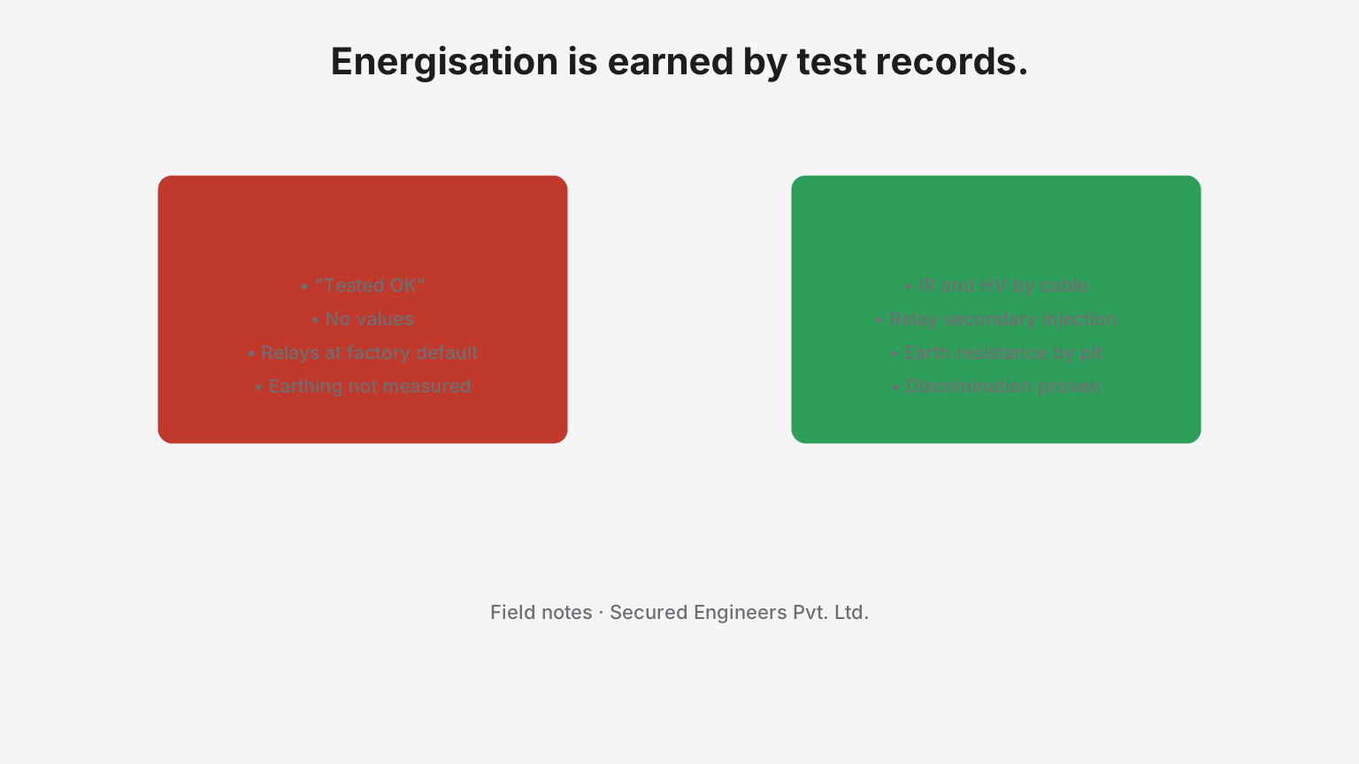
An electrical installation is not finished when the last cable is terminated; it is finished when every test has a value against it and the Electrical Inspector has seen the record. This is the sequence our electrical engineers follow on an industrial installation, and what is recorded at each step.
1. Before energisation — visual and mechanical
Every termination torqued and checked; clearances and creepage in the switchgear; cable glands and earthing of armour; panel labelling against the single-line diagram; interlocks mechanically proved; the substation's own lighting, ventilation, fire protection and access in place. Recorded on a checklist the inspector can read.
2. Insulation resistance and high-voltage tests
Insulation resistance on every cable and every panel section, phase to phase and phase to earth, with the values recorded — not "OK" — against the cable schedule. High-voltage withstand on HT cables and switchgear at the test voltage the standard specifies, with leakage recorded. A cable that fails here is replaced before it is energised, not after.
3. Earthing — measured, by pit, and at the terminal
Earth resistance at every electrode with the pit number, and the combined value at the main earthing terminal; continuity of the equipotential bonding to panels, trays, structural steel and equipment. The values go on a register the CEIG submission includes and the AMC re-tests before each monsoon.
4. Transformers
Ratio and vector group, winding and core insulation, oil breakdown voltage (and dissolved-gas analysis on larger units), Buchholz and temperature protections functioned, tap changer operated through its range, neutral earthing checked. The factory test certificate is filed with the site results.
5. Protection — secondary injection and discrimination
Every protection relay injected at its settings — overcurrent, earth fault, differential where fitted — with pickup and operating time recorded, and the settings compared with the coordination study. Then discrimination proved: a simulated fault on a downstream feeder trips its breaker and leaves the incomer closed. Relays left at factory defaults are the most common way a plant loses all its power to one motor fault.
6. Panels — function and interlocks
Each breaker operated electrically and manually; indications and metering read; incomer and bus-coupler interlocks proved; APFC panel commissioned against a live power-factor reading so the steps correct the actual load; motor control centres run through their starters with the drives' parameters recorded.
7. DG sets and changeover
Load test for the duration the standard requires with voltage, frequency and temperatures recorded; AMF sequence proved under a simulated grid failure — start, transfer, retransfer, cool-down; synchronising proved where sets run in parallel; acoustic enclosure and exhaust as the pollution-board consent requires.
8. Lighting, small power and emergency systems
Lux levels measured against the design by area; emergency lighting and exit signs run on battery for the required duration; socket circuits polarity- and earth-loop-tested.
9. Thermography at first load
Every panel, bus-duct joint and termination scanned under load after energisation; hot spots corrected and re-scanned. Recorded as the baseline the AMC compares against.
10. The file for the inspector
The licensed contractor's completion and test report; the results above with values; the approved drawings and any as-built variance; equipment test certificates; the earthing register; the protection settings. Presented at inspection, not assembled after the shortfall letter. The CEIG guides record what each state's inspectorate asks for; the readiness checker runs the same list.
What we commonly find on installations offered for inspection
- "Tested OK" with no values.
- Relays at factory settings; no coordination study.
- Earthing never measured, or measured once, in the monsoon.
- DG set run for a minute, never under load.
- Test reports signed by a contractor who did not hold the licence.
The testing and commissioning page describes the scope as a service; the electrical page and its sub-services the installation it tests.
Frequently asked
What electrical test records does the CEIG ask for?
Insulation-resistance and high-voltage test results for cables and switchgear, earth-resistance values by electrode and at the main terminal, relay test records with the settings applied, transformer test results, and the licensed contractor's completion and test report. A value the inspector cannot see is a test that was not done.
What is a discrimination check?
Proof that a fault trips the breaker nearest to it and not the one upstream — the relay and breaker settings coordinated so that a fault on one feeder does not black out the plant. It is checked by secondary injection against the coordination study, not assumed from the settings.
More insights
The Line Item Nobody Reads: How Power Factor Quietly Inflates Industrial Bills in Punjab, Haryana & UP
Your plant pays for kVAh, not kWh — and if your power factor drifts below the incentive band, you are donating lakhs a year to the DISCOM. What PF actually is, why induction-motor-heavy plants drift, and the 12–24 month payback fix.
ElectricalTwo Panels, Same Price, Ten Years Apart in Life: Reading an LT Panel Spec
Every LT panel quote says 'as per IS/IEC'. The difference between a panel that serves twenty years and one that becomes a maintenance hazard hides in four unglamorous specifications: form of separation, IP rating, fault withstand, and type-testing.