
Your Section Drawing Promised a 3.2m Ceiling. The Ducts Ate 40cm of It.
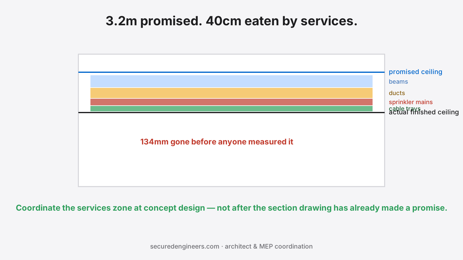
Every architect has lived this moment: a beautiful section drawing, a client sign-off on a 3.2-metre clear ceiling height, a rendering that sells the space — and then, months later, a site meeting where someone asks why the finished ceiling sits at 2.8 metres. The answer is almost always the same. The section drawing was drawn before anyone asked where the ducts, the sprinkler mains, the cable trays and the structural beams were actually going to run.
This is not a construction-stage problem. It is a design-stage decision that nobody made — and by the time it surfaces, the fix costs a redesign, a client conversation nobody wants to have, or both.
Where the height actually goes
Above every false ceiling, several systems compete for the same vertical zone — and none of them are optional:
| System | Typical space claim | Why it can't just "fit around" the others |
|---|---|---|
| Structural beams | 300–900mm depth, fixed by span | Set by the structural engineer, effectively non-negotiable once cast |
| Primary HVAC ducts | 200–450mm depth per main run | Sized by airflow — undersizing means noise and poor comfort, not a space saving |
| Fire sprinkler mains & branches | 100–200mm, plus code-mandated clearances | Positioned by NBC coverage rules, not by what's convenient |
| Electrical cable trays | 100–150mm | Needs separation from other services for safety and maintenance access |
| Plumbing/drainage (where routed above) | Slope-dependent, can dominate a zone | Gravity drainage cannot be "adjusted" the way ducting sometimes can |
Drawn separately, on separate layers, by separate consultants who never sat in the same coordination review — these systems don't know they're competing for the same 40cm. The section drawing that promised 3.2m was drawn against the structural grid alone, with an assumed (and usually optimistic) allowance for "services" that nobody actually calculated.
Why this is a sequencing problem, not a skill problem
The architects who lose height are not bad architects. They are working in a sequence where MEP gets engaged after the concept design is client-approved — which means every MEP requirement discovered afterward is treated as an intrusion on a finished design, not an input to one. The result is the same conversation on every project: "can you fit it in a smaller zone," asked of an engineer who cannot shrink a fire main's required clearance any more than the architect could shrink a structural beam's span.
The fix is not asking MEP to compress. It is inviting MEP into the room during concept design, so the section drawing that goes to the client already reflects a real, coordinated ceiling void — not an aspiration.
What early MEP coordination actually looks like
- A services-zone allowance set from real numbers, not a rule-of-thumb 600mm — calculated from the actual duct sizing, sprinkler layout and cable-tray routing for that specific floor plate and occupancy, before the section is finalised
- One combined reflected-ceiling drawing showing structure, ducts, sprinklers, trays and lighting together — the same coordinated-drawing discipline that prevents the on-site ceiling war, just moved earlier, into design instead of construction
- Critical zones sectioned in detail — corridors, lobby crossings, riser-adjacent areas — wherever multiple services converge and the generic allowance won't hold
- A height budget the client sees honestly, including the trade-offs: a taller floor-to-floor height costs more structure and façade; a tighter services zone may mean exposed ceilings or a different duct strategy in specific rooms
- MEP input on structural grid and beam depth at the same stage as the architectural concept, not after — beam depth and services-zone depth are the same design conversation, held separately by habit
The alternatives when height is already promised
If a project inherits a committed ceiling height and MEP is discovering the conflict late, the honest options — worse than getting it right early, but real — are: exposing selected ceiling zones (a design choice, not a failure, if made deliberately); re-routing primary ducts to a different path (often means a different plant-room strategy); locally increasing floor-to-floor height in the affected zone only; or, in the worst case, accepting a lower finished ceiling and having the difficult client conversation. All four are cheaper the earlier they're identified — a redesign three weeks into construction costs an order of magnitude more than the same redesign as a markup on a concept drawing.
What this means for how architects should brief MEP
- Bring MEP into the first design workshop, not the first coordination meeting — the difference is whether services shape the section or react to it
- Ask for the services-zone number early, and treat it as a real design constraint, the same way a structural span or a fire-egress width is treated
- Flag your highest-risk zones — double-height lobbies, service corridors, riser crossings — for detailed early coordination rather than generic allowance
- Keep one live coordinated model (or drawing set) that both architectural and MEP teams update — not two parallel sets reconciled occasionally
We run MEP design as a concept-stage discipline specifically because of this — the earlier we're in the room, the more of the promised height actually survives to the finished building. For architects and design teams looking for the underlying clearance numbers directly, our Architect & Design Resource Hub has room-by-room MEP clearance guides.
FAQs
How much ceiling void should I allow for MEP services?
There's no reliable universal number — it depends on occupancy, HVAC system type, span, and sprinkler design. A generic 600mm allowance is a starting assumption to validate, not a figure to design around blind. Get a real calculation from the MEP team before the section is finalised.
Can ducts and sprinkler mains share the same ceiling zone?
They typically occupy the same general void but at different levels with required clearances between them and from the structure — coordinated in section, not simply layered by assumption.
What's the cheapest stage to fix a services-zone conflict?
Concept design, by a wide margin — a section-drawing adjustment costs nothing but a markup; the same fix during construction means demolition, re-routing and schedule slippage.
Can you join our design team at concept stage for MEP coordination?
Yes — that's exactly when we're most useful. Bring us in early.
More insights
A Digital Twin Is Not a 3D Model. It Is a Live Data Obligation.
Digital twins are sold as a visualisation. What makes one useful is the live data behind it — which means metering, BMS integration and an as-built model that stays true. Most twins fail not at creation but at maintenance.
Design & CoordinationYour Municipality Already Auto-Checks the Building Envelope. It Doesn't Auto-Check Your MEP.
Many Indian municipal corporations now run Auto-DCR software that automatically checks a building's plan against local byelaws — setbacks, FAR, height. It's a genuine, useful system. It's also not an MEP code-checker, and treating BIM as if it feeds an automated MEP approval process overstates where the technology actually is today.